* converter/ibm_5291: Configurator support

- added layout data to info.json file
- corrected keyboard_folder value

* converter/ibm_5291: readme cleanup

- Fixed "image" url (target of link was a web page; changed markdown formatting to text link)
- Sentence capitalization fixes
- markdown formatting fixes for readability
72 lines
1.9 KiB
Markdown
72 lines
1.9 KiB
Markdown
# IBM 5291 keyboard converter
|
||
|
||
[IBM 5291](https://deskthority.net/wiki/IBM_Model_F#IBM_5291_Keyboard)
|
||
|
||
A converter for the eponymous keyboard.
|
||
|
||
Keyboard Maintainer: [Listofoptions](https://github.com/listofoptions)
|
||
Hardware Supported: IBM 5291, Teensy 2.0
|
||
|
||
Make example for this keyboard (after setting up your build environment):
|
||
|
||
make converter/ibm_5291:default
|
||
|
||
See the [build environment setup](https://docs.qmk.fm/#/getting_started_build_tools) and the [make instructions](https://docs.qmk.fm/#/getting_started_make_guide) for more information. Brand new to QMK? Start with our [Complete Newbs Guide](https://docs.qmk.fm/#/newbs).
|
||
|
||
|
||
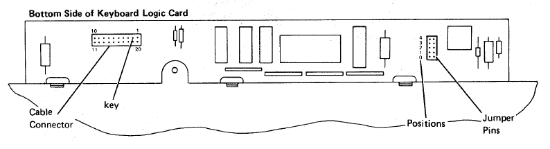
The pinout is as follows:
|
||
|
||
IBM−5291−Cable to Pinhead−14
|
||
|
||
| pin | description
|
||
----|------------------------
|
||
1 | GND
|
||
2 | NC
|
||
3 | GND
|
||
4 | GN)
|
||
5 | +5V
|
||
6 | D0
|
||
7 | D1
|
||
8 | D2
|
||
9 | D3
|
||
10| D4
|
||
11| D5
|
||
12| D6
|
||
13| Strobe
|
||
14| Out
|
||
|
||
The pins on this connector are organized
|
||
|
||
|
||
IBM−5291−2 Cable with DB15M connector
|
||
|
||
| pin | description
|
||
----|-------------
|
||
|1,2,3 | GND
|
||
|4 | +5V
|
||
|5 | D0
|
||
|6 | D1
|
||
|7 | D2
|
||
|8 | D3
|
||
|9 | D4
|
||
|10 | D5
|
||
|11 | D6
|
||
|12 | Strobe
|
||
|13 | Out
|
||
|14 | PE
|
||
|15 | NC
|
||
|
||
The above connector is actually numbered so it should be easier to determine
|
||
where the needed connections are.
|
||
|
||
To connect to the teensy, the following are pins are needed (if you should choose not set your own):
|
||
|
||
* PB0 -> PB6 are connected to D0 -> D6
|
||
* +5V is connected to the corresponding teensy pin
|
||
* gnd is as well, only one of the gnd pins needs to be connected though.
|
||
* strobe is connected to pin PD1
|
||
* data is connected to PD0
|
||
* PE does not need to be connected to anything, but it could also be connected to gnd
|
||
|
||
sources:
|
||
http://www.retrocomputing.eu/documents/5291_MaintenanceLibrary.pdf
|